Pulse Valve
-
The Working Principle of Pulse Valves: Mechanism, Stages and Core Components
Pulse valves are the core control components of industrial pulse jet cleaning systems, widely used in dust collection equipment to realize efficient cleaning of filter bags. Their core function is to convert continuous compressed air into intermittent, high-speed pulse airflow through precise on-off control. The stable and rapid operation of pulse valves relies on a scientific pressure difference control mechanism, with the diaphragm assembly and solenoid pilot valve playing a pivotal role. This article will elaborate on the working principle of pulse valves in detail, including their core component collaboration and the three key stages of operation.Core Components Involved in the Working Mechanism
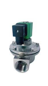
Before exploring the working principle, it is necessary to understand the core components that drive the operation of pulse valves, as their coordinated work ensures the valve’s reliable performance. Industrial pulse valves (mainly pilot-operated types, the most widely used category) are composed of four key parts:The valve body serves as the main structural framework, providing channels for compressed air flow and mounting positions for internal components. The solenoid pilot valve acts as the “control switch,” responsible for receiving electrical signals from the dust collector controller and regulating the pressure in the diaphragm upper chamber. The diaphragm assembly (including the pulse valve diaphragm) is the core executive component, whose movement directly controls the on-off of the main air channel. The reset spring assists the solenoid pilot valve in resetting after power failure, ensuring the diaphragm returns to the closed position stably.Among these components, the diaphragm is the key vulnerable part. Made of rubber, PTFE, or fabric-reinforced materials, it must have excellent elasticity, wear resistance, and fatigue resistance to withstand frequent pressure changes and cyclic movements. The solenoid pilot valve, on the other hand, requires high response speed to ensure the pulse valve can complete the on-off action in milliseconds.Three Stages of Pulse Valve Operation
The working process of pulse valves is based on the pressure difference control principle, which can be clearly divided into three stages: standby, opening (pulse jet), and resetting. Each stage is driven by the cooperative operation of the solenoid pilot valve and diaphragm, realizing precise control of compressed air.1. Standby Stage: Pressure Balance Maintains Closure
In the standby state, the dust collector is in normal filtration mode, and the pulse valve remains closed to avoid unnecessary air consumption. At this time, the solenoid pilot valve is de-energized and in the closed position, blocking the exhaust channel connected to the upper chamber of the diaphragm. Compressed air from the air source enters the upper chamber of the diaphragm through a built-in small air passage in the valve body, while a portion of the air remains in the lower chamber of the diaphragm.Due to the structural design, the pressure in the upper chamber of the diaphragm is slightly higher than that in the lower chamber. This pressure difference generates a downward force, pressing the diaphragm tightly against the valve seat of the main air channel. As a result, the main air channel is completely closed, and compressed air cannot pass through, ensuring the dust collector can stably filter dust without air leakage.2. Opening Stage: Reverse Pressure Difference Triggers Pulse Jet
When the filter bags of the dust collector accumulate a certain amount of dust, the controller sends an electrical cleaning signal to the solenoid pilot valve. Upon receiving the signal, the solenoid pilot valve is instantly energized and opens, connecting the upper chamber of the diaphragm to the atmospheric environment through the exhaust channel.The compressed air in the upper chamber of the diaphragm is quickly discharged to the atmosphere through the opened pilot valve, causing the pressure in the upper chamber to drop sharply in a short time. Meanwhile, the pressure in the lower chamber of the diaphragm remains unchanged (consistent with the air source pressure). This rapid pressure change forms a reverse pressure difference between the upper and lower chambers of the diaphragm, with the upward force in the lower chamber overcoming the downward force in the upper chamber.Under the action of this reverse pressure difference, the diaphragm is pushed upward rapidly, opening the main air channel of the pulse valve. Compressed air from the air source then rushes through the main channel to the blowpipe at high speed, generating a strong pulse airflow. This airflow is ejected through the nozzles on the blowpipe, penetrating the filter bags and causing them to expand and vibrate, thereby blowing off the dust accumulated on the surface of the filter bags to achieve cleaning.The duration of this opening stage (i.e., the pulse width) is usually adjustable between 0.1-0.5 seconds, depending on the dust properties and filter bag specifications. High-quality pulse valves can complete the opening action in tens of milliseconds, ensuring the pulse airflow is concentrated and powerful.3. Resetting Stage: Pressure Recovery Restores Closure
After the preset cleaning cycle ends, the dust collector controller cuts off the power supply to the solenoid pilot valve. The solenoid pilot valve resets under the action of the internal reset spring, closing the exhaust channel again and blocking the connection between the upper chamber of the diaphragm and the atmosphere.Compressed air from the air source re-enters the upper chamber of the diaphragm through the built-in small air passage, gradually increasing the pressure in the upper chamber. As the pressure rises, the pressure difference between the upper and lower chambers is restored to the standby state, and the diaphragm is pressed back to the valve seat by the downward pressure of the upper chamber, closing the main air channel.At this point, the pulse valve completes a full working cycle and returns to the standby state, waiting for the next cleaning signal. The entire process is repeated continuously, ensuring the dust collector maintains stable filtration efficiency by regularly cleaning the filter bags. -
Selection Guide and Maintenance Tips for Pulse Valve Diaphragms
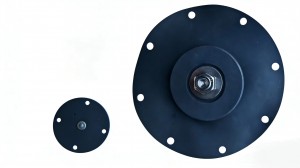
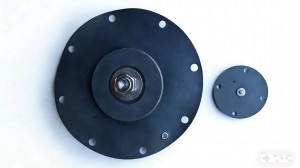
Pulse valve diaphragms are vulnerable components in dust collection systems, and their service life is affected by material selection, working conditions, and maintenance practices. Proper selection and regular maintenance can significantly extend the diaphragm’s lifespan, reduce downtime, and lower operating costs. This article provides a comprehensive guide to diaphragm selection and maintenance.Key Factors for Diaphragm Selection
The selection of pulse valve diaphragms should be based on actual working conditions, focusing on the following four core factors:Material compatibility is the primary consideration. It is necessary to ensure that the diaphragm material is compatible with the working medium (compressed air, dust, or other gases) and the surrounding environment. For example, in chemical plants with corrosive gases, PTFE diaphragms should be selected; for general dust collection systems, rubber diaphragms can meet the requirements. In oil-containing compressed air environments, nitrile elastomeric diaphragms with oil resistance are preferred.Temperature range is another critical factor. Diaphragm materials have specific temperature tolerance limits, and exceeding this range will accelerate material degradation, leading to premature cracking or hardening. For high-temperature environments such as metallurgical or cement plants, high-temperature resistant materials like PTFE or special rubber should be used; for normal temperature environments, ordinary rubber diaphragms are sufficient. It is recommended to reference the manufacturer’s specifications to ensure temperature compatibility.Application pressure must match the diaphragm’s design pressure. Exceeding the maximum pressure rating will cause diaphragm rupture, while insufficient pressure may affect sealing performance. Fabric-reinforced diaphragms are suitable for high-pressure systems (above 0.6MPa), while ordinary rubber diaphragms are applicable for medium and low-pressure systems (0.3-0.6MPa). It is essential to confirm the system pressure before selection.Flexibility and endurance are crucial for long-term operation. In systems with high-frequency pulse cycles (e.g., more than 10 times per minute), diaphragms with good fatigue resistance, such as fabric-reinforced or high-quality elastomeric types, should be selected. These materials can maintain elasticity and sealing performance after millions of cycles, reducing replacement frequency. -
Pulse Valve Diaphragms – Core Principles and Material Classification
Pulse Valve Diaphragms – Core Principles and Material Classification
As the key component of pulse jet solenoid valves, pulse valve diaphragms play a decisive role in the stable operation of dust collection systems. Acting as a “flexible gate” that controls the on-off of compressed air, their performance directly affects the cleaning efficiency of filter bags, energy consumption of the system, and overall maintenance costs. To fully understand the functionality of pulse valve diaphragms, it is essential to explore their working mechanism and material classifications.Working Principle of Pulse Valve Diaphragms
Most industrial pulse valves adopt a pilot-operated design, and the diaphragm is the core executing part of this design, realizing rapid opening and closing through pressure difference control. The working process can be divided into three stages:In the standby state, the solenoid pilot valve is closed, blocking the exhaust channel above the main diaphragm. Compressed air enters the upper chamber of the diaphragm through a small air passage, creating a higher pressure above the diaphragm than below. This pressure difference presses the diaphragm tightly against the air outlet, keeping the pulse valve closed and preventing air leakage.When the dust collector controller sends a cleaning signal, the solenoid pilot valve is energized and opens immediately. The compressed air in the upper chamber of the diaphragm is quickly discharged through the exhaust channel, causing the pressure above the diaphragm to drop sharply. Meanwhile, the pressure below the diaphragm remains unchanged, forming a reverse pressure difference that pushes the diaphragm upward, opening the air outlet. Compressed air then rushes through the outlet to the blowpipe at high speed, generating a strong pulse airflow to blow off dust attached to the filter bags.After the cleaning cycle (usually 0.1-0.5 seconds, adjustable), the controller cuts off the power to the solenoid pilot valve. The pilot valve resets under the action of a spring, blocking the exhaust channel again. Compressed air refills the upper chamber of the diaphragm, restoring the pressure balance and pressing the diaphragm back to the closed position, waiting for the next cleaning command. In essence, the diaphragm’s movement is driven by pressure difference controlled by electromagnetic force, achieving precise and rapid pulse blowing.Common Material Types and Characteristics
The selection of diaphragm materials is closely related to working conditions such as medium, temperature, and pressure. The following are four common types of pulse valve diaphragm materials and their application scenarios:Rubber diaphragms are the most widely used type due to their excellent elasticity, wear resistance, and cost-effectiveness. Suitable for general industrial dust collection environments with normal temperature and non-corrosive compressed air, they can maintain good sealing performance under frequent cyclic operations. However, they are not recommended for high-temperature or chemical-corrosive conditions.PTFE (Teflon) diaphragms excel in chemical resistance and high-temperature tolerance. They can withstand the erosion of strong acids, alkalis, and other corrosive substances, and maintain stability in extreme temperature environments. These diaphragms are ideal for chemical, pharmaceutical, and other industries where corrosive media are involved, though they have relatively lower elasticity compared to rubber.Fabric-reinforced diaphragms are composed of rubber or elastomer with nylon or polyester fabric as the reinforcing layer. This structure enhances stiffness and elongation, making them suitable for high-pressure applications. They exhibit excellent durability under frequent cyclic loads, reducing the risk of deformation or rupture, and are commonly used in heavy-duty dust collection systems with high-pressure air sources.Elastomeric diaphragms, made from high-quality materials such as nitrile or neoprene, offer superior sealing performance and flexibility. They can be molded into various shapes to fit different valve structures, making them suitable for high-precision pneumatic systems. Nitrile elastomeric diaphragms have good oil resistance, while neoprene ones perform well in ozone and aging resistance, adapting to specific harsh working conditions. -

Technical Analysis and Application of DMK – Z – 50 Electromagnetic Pulse Valve
The DMK – Z – 50 electromagnetic pulse valve is a key component in numerous industrial applications, especially those related to dust removal and pneumatic control. This article delves deeper into its technical aspects, installation requirements, maintenance considerations, and a comparison with similar products in the market.Technical Specifications
- Voltage Options: The DMK – Z – 50 offers a variety of voltage options to suit different power supply requirements. It can be configured to operate on 24 VDC, 110V AC, 120V AC, 220V AC, or 230V AC (50/60 Hz). This flexibility makes it compatible with a wide range of industrial electrical systems. For example, in a factory with a predominantly 220V AC power supply, the valve can be easily integrated without the need for complex voltage conversion systems.
- Connection Size: With a DN50 (G2”) inlet and outlet threaded port size, the valve is designed to handle a significant volume of compressed air. This size is suitable for applications where a relatively large – scale air flow is required, such as in large – capacity dust collectors or high – volume pneumatic conveying systems.
- Working Pressure Range: It has a working pressure range of 0.1 to 0.8 MPa. This wide pressure range allows the valve to be used in diverse industrial scenarios. In low – pressure applications like some food and beverage production lines where gentle air pulses are needed, the valve can operate effectively at the lower end of the pressure range. On the other hand, in more demanding applications such as heavy – duty mining dust collection, it can handle the higher pressures without performance degradation.
- Diaphragm Material: The diaphragm of the DMK – Z – 50 is typically made of NBR (Nitrile Butadiene Rubber). NBR is known for its excellent resistance to oil, fuel, and abrasion, which are common factors in industrial environments. This material choice ensures that the diaphragm can withstand the harsh conditions of continuous operation, resulting in a long – lasting and reliable valve.
Installation Guide
- Pre – installation Checks: Before installing the DMK – Z – 50, it is essential to check the valve for any visible damage that may have occurred during transportation. Inspect the body, diaphragm, and electromagnetic coil for any signs of cracks, dents, or loose parts. Also, ensure that all the necessary installation accessories, such as gaskets and mounting brackets, are present.
- Cleaning the Pipeline: The air supply pipeline should be thoroughly cleaned before installing the valve. Any debris, dirt, or moisture in the pipeline can cause damage to the valve’s internal components or affect its performance. Use compressed air or appropriate cleaning agents to remove any contaminants.
- Mounting the Valve: The valve should be mounted in a location that allows for easy access for maintenance and inspection. Ensure that the valve is installed in the correct orientation, with the inlet and outlet ports properly aligned with the pipeline. Use the provided mounting brackets and fasteners to securely attach the valve to the support structure.
- Electrical Connection: When connecting the electrical wires to the electromagnetic coil, follow the wiring diagram provided with the valve. Make sure that the electrical connections are secure and properly insulated. If the voltage is above 36V, it is recommended to ground the valve to ensure electrical safety.
Maintenance Tips
- Regular Inspection: Periodically inspect the valve for any signs of wear or damage. Check the diaphragm for cracks, tears, or signs of excessive wear. Inspect the electromagnetic coil for any overheating or electrical issues. Look for any air leaks around the valve body or connections.
- Cleaning: Clean the valve regularly to remove any accumulated dust, dirt, or debris. Use a soft brush or compressed air to clean the internal and external parts of the valve. This helps to maintain the valve’s performance and prevent clogging of the air passages.
- Diaphragm Replacement: If the diaphragm shows signs of significant wear or damage, it should be replaced promptly. The replacement process is relatively straightforward, but it is important to use a genuine replacement diaphragm to ensure proper fit and performance.
- Testing: Periodically test the valve’s operation to ensure that it is functioning correctly. Use a pulse control instrument to send electrical signals to the valve and check that it opens and closes properly. Monitor the air flow and pressure to ensure that they are within the specified range.
Comparison with Similar Products
- Response Time: Compared to some other electromagnetic pulse valves in the market, the DMK – Z – 50 offers a faster response time. This means that it can open and close more quickly in response to an electrical signal, which is crucial for applications that require precise timing of air pulses. For example, in a high – speed dust collection system where rapid cleaning of filter bags is essential, the fast response time of the DMK – Z – 50 can result in more efficient dust removal.
- Durability: Thanks to its high – quality materials and robust construction, the DMK – Z – 50 has a longer service life compared to some similar products. The use of NBR diaphragms and aluminum alloy bodies contributes to its durability, making it suitable for use in harsh industrial environments where other valves may fail prematurely.
- Energy Efficiency: The DMK – Z – 50 is designed to be energy – efficient, consuming less power during operation. This is an advantage over some older – style or less – efficient pulse valves, as it helps to reduce the overall energy consumption of the system and lower operating costs.
In summary, the DMK – Z – 50 electromagnetic pulse valve is a technically advanced and reliable product. By understanding its technical specifications, following proper installation and maintenance procedures, and comparing it with other products, industrial users can make informed decisions about its use in their specific applications, ensuring optimal performance and long – term reliability. -

DMK – Z – 50 Electromagnetic Pulse Valve: A High – Performance Solution
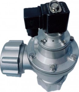
In the realm of industrial dust collection and pneumatic control systems, the DMK – Z – 50 electromagnetic pulse valve stands out as a reliable and efficient component. This valve plays a crucial role in ensuring the smooth operation of various industrial processes, especially those related to dust removal and pneumatic conveying.Design and Structure
The DMK – Z – 50 is designed with precision and durability in mind. Its body is typically made of high – quality aluminum alloy, which not only provides excellent corrosion resistance but also makes the valve lightweight yet sturdy. The internal structure features a diaphragm that is the heart of the valve’s operation. The diaphragm is crafted from a special rubber compound that can withstand high pressures and frequent cycling, ensuring a long service life.The valve is equipped with an electromagnetic coil. When an electrical signal is received, the coil generates a magnetic field that activates the valve. This design allows for quick and accurate control of the valve’s opening and closing, which is essential for efficient system operation.Working Principle
The working principle of the DMK – Z – 50 is based on the interaction between the electromagnetic coil and the diaphragm. In its normal state, the diaphragm seals the valve outlet, preventing the flow of compressed air. When the pulse control instrument sends an electrical signal to the electromagnetic coil, the coil energizes and creates a magnetic force. This magnetic force pulls the armature, which in turn opens the diaphragm.Once the diaphragm is opened, compressed air can flow through the valve at a high velocity. This sudden burst of air is used for various purposes, such as cleaning dust – laden filters in a dust collector. When the electrical signal from the control instrument stops, the electromagnetic coil de – energizes, and the diaphragm returns to its original position, closing the valve and halting the air flow.Performance Features
- Fast Response Time: The DMK – Z – 50 offers an extremely fast response time, typically within milliseconds. This rapid response is crucial for applications where precise timing of air pulses is required, such as in high – speed dust collection systems. For example, in a large – scale industrial dust collector, the quick opening and closing of the valve ensure that each filter bag is cleaned effectively in a short period.
- High Pressure Resistance: It can withstand a wide range of working pressures, usually from 0.1 MPa to 0.8 MPa. This high – pressure tolerance makes it suitable for use in different industrial environments, whether it’s a low – pressure pneumatic system in a food processing plant or a high – pressure application in a mining dust collection setup.
- Long – Lasting Durability: Thanks to its high – quality materials and robust construction, the DMK – Z – 50 has a long service life. The diaphragm, in particular, is designed to endure millions of cycles without failure. In a continuous – operation dust collection system in a cement factory, the valve can operate for years with minimal maintenance, reducing downtime and maintenance costs.
- Energy – Efficient Operation: The valve is designed to be energy – efficient. It only consumes power when the electromagnetic coil is activated to open the valve. Once the air pulse is completed, the coil de – energizes, saving energy. This energy – saving feature is not only environmentally friendly but also helps to reduce the overall operating costs of the system.
-
Significant Performance Advantages of DMF – ZM – 40 Pulse Valve
The DMF – ZM – 40 pulse valve is highly favored in industrial applications due to its series of remarkable performance advantages, which make it stand out among similar products.
From the perspective of sensitivity, the DMF – ZM – 40 pulse valve responds extremely quickly to the electrical signals of the pulse blower control instrument. As soon as the electrical signal is received, the moving core of the electromagnetichead can quickly move, opening the exhaust hole of the rear chamber, causing the diaphragm to rapidly move backward to achieve the blower action. The entire process is completed almost instantaneously. This high sensitivity ensures that the cleaning and blower actions can be carried out promptly and accurately, effectively avoiding the problem of insufficient dust removal due to delayed response, thereby ensuring the efficient operation of the dust collector.
In terms of exhaust volume, the DMF – ZM – 40 pulse valve has outstanding performance. Its design structure enables it to provide a large exhaust channel when in the open state, allowing compressed air to be rapidly and in large quantities ejected through the valve outlet. The powerful blower airflow can forcefully impact the dust on the surface of the filter bag, completely removing it, even the stubbornly adhered dust is difficult to resist. Compared with some similar products, it can complete the dust removal of the same area filter bag in a shorter time, greatly improving the dust removal efficiency and reducing the maintenance time and cost of the equipment.The working stability is also a major highlight of the DMF – ZM – 40 pulse valve. It is manufactured with high-quality materials, such as the diaphragm using imported nitrile rubber, which has good flexibility and wear resistance, capable of withstanding frequent opening and closing actions, ensuring that it will not crack or damage during long-term use. At the same time, its internal structure has been carefully designed, with a close and reasonable fit between each component, maintaining a stable working state under different working environments and pressure conditions. Whether in harsh environments with high temperature and high humidity, or under high pressure and high-frequency blower operation intensity, the DMF – ZM – 40 pulse valve can operate reliably, providing a strong guarantee for the continuity of industrial production.
In addition, the DMF – ZM – 40 pulse valve also has great convenience in installation, use, and maintenance. It has fixed nuts for installation at both the inlet and outlet ends, making the installation connection between the air box and the dust collector blower pipe simple and quick, effectively shortening the installation time. During use, its working principle is simple and easy to understand, and the operating state is easy to monitor and control. When maintenance is needed, due to its reasonable structure design, each component is easy to disassemble and replace, allowing maintenance personnel to quickly locate and solve problems, reducing the difficulty and downtime of equipment maintenance and improving the production efficiency of the enterprise.
-

The wide range of applications for the DMF – ZM – 40 pulse valve
The DMF – ZM – 40 pulse valve, with its outstanding performance, has extensive and crucial applications in numerous industrial fields, becoming an important component for ensuring the production environment and equipment operation.
In the field of dust removal, especially in the pulse bag-type dust collector system, the DMF – ZM – 40 pulse valve is regarded as the core component. As the “switch” of the dust cleaning blow-off system’s compressed air, it is precisely controlled by the pulse blow-off controller’s output signal, and it performs dust cleaning by blowing on the filter bags row by row (section by section). In boiler dust collectors, it can promptly remove a large amount of dust generated during boiler operation, preventing dust accumulation from affecting the thermal exchange efficiency and safe operation of the boiler; in medium-frequency electric furnace dust collectors, in the presence of high-temperature and high-concentration dust environment, the DMF – ZM – 40 pulse valve can still work stably, ensuring the air quality in the electric furnace workshop and protecting the health of workers. Moreover, in various dust removal equipment such as casting-specific dust collectors, woodworking-specific dust collectors, and mining-specific dust collectors, its busy “presence” can be seen, creating a clean environment for industrial production.
In environmental protection waste gas treatment, the DMF – ZM – 40 pulse valve also plays an important role. For example, in plasma waste gas purification equipment and spray towers, it participates in the waste gas treatment process. By controlling the blow-off of compressed air, it assists the purification equipment in capturing and separating pollutants in the waste gas, improving the waste gas purification efficiency, and helping enterprises meet environmental protection emission standards and reducing pollution to the atmospheric environment.In some industrial production processes that require precise control of gas flow and pressure, the DMF – ZM – 40 pulse valve also performs well. For instance, in chemical production, certain reaction processes require precise control of the gas addition amount and time intervals. The DMF – ZM – 40 pulse valve can accurately open and close according to the set program, providing stable gas supply conditions for chemical reactions, ensuring the smooth progress of chemical production and the stability of product quality.
-
In-depth Analysis of the Working Principle of DMF – ZM – 40 Pulse Valve
In industrial dust removal systems, the DMF – ZM – 40 pulse valve plays a crucial role, and its efficient and stable operation relies on a unique and ingenious working principle.
From a structural perspective, the DMF – ZM – 40 pulse valve is mainly divided into two gas chambers by a diaphragm. When the entire system is connected to compressed air, the compressed air will slowly enter the rear gas chamber through the throttle hole. At this time, the pressure in the rear gas chamber gradually increases until it tightly presses the diaphragm assembly against the output port of the valve, thus putting the electromagnetic pulse valve in the initial “closed” state, like a meticulous guard, firmly controlling the flow of compressed air.
When the pulse blowing control instrument sends an electrical signal, this signal is like giving the pulse valve an “open” instruction. The electrical signal causes the armature of the electromagnetic pulse valve to move rapidly backward, thereby opening the exhaust hole of the rear gas chamber. The air in the rear gas chamber is rapidly expelled in a short period of time, and the pressure instantly drops. Under the action of the pressure difference, the diaphragm assembly moves backward, and the compressed air that was previously blocked rushes out through the valve output port at high speed. At this time, the electromagnetic pulse valve enters the “open” state, and the powerful blowing airflow cleanses the filter bag, blowing off the dust adhering to the surface of the filter bag, ensuring the efficient operation of the dust removal system.
When the electrical signal from the pulse blowing control instrument disappears, the armature of the electromagnetic pulse valve returns to its initial position under the action of the reset device, and the exhaust hole of the rear gas chamber closes. The rear gas chamber then begins to intake air through the throttle hole, and the pressure gradually rises. The diaphragm assembly re-contacts the output port of the valve again, and the electromagnetic pulse valve returns to the “closed” state, waiting for the next blowing command to arrive. This precise and efficient working mode enables the DMF – ZM – 40 pulse valve to operate stably in the dust removal and blowing system of the pulse bag dust collector, continuously contributing to the purification of industrial production environments.
-
DMF-Z-50: The Vanguard of Dust Removal in Technological Innovation and Industry Practice
In the wave of pursuing high efficiency and environmental protection in the industrial dust removal field, DMF-Z-50 has become the top choice for numerous enterprises with its outstanding performance. From technological breakthroughs to practical applications, it is redefining the standards of industrial dust removal as an innovator.
I. In – depth Analysis of Core Technical ParametersThe core technical parameters of DMF-Z-50 are the foundation of its high efficiency. With a diameter of 50mm, this size design enables it to be compatible with the pipelines of various specifications of dust removal equipment, ensuring the efficient transmission of compressed air. The working pressure range is usually 0.4 – 0.8MPa. This wide pressure adaptation range allows DMF-Z-50 to maintain stable blowing even in low-pressure environments and achieve strong power output under high-pressure requirements.In terms of electrical performance, DMF-Z-50 supports multiple voltage specifications, commonly including DC24V, AC220V, etc., meeting the power supply needs of different industrial scenarios. Its response time is extremely short, only taking dozens of milliseconds. This means that after the dust removal system issues an instruction, it can complete the blowing action instantly, greatly improving the dust removal efficiency. In addition, the service life of this pulse valve can reach more than millions of times. Even under high-frequency usage conditions, it can still maintain stable performance.II. Common Faults and Efficient Troubleshooting SolutionsAlthough DMF-Z-50 has stable performance, faults may still occur after long-term use. One of the most common problems is that the pulse valve fails to open normally. This may be caused by a burned-out electromagnetic coil, a short circuit in the control circuit, or a blocked air path. When troubleshooting, first check the resistance value of the electromagnetic coil. If the resistance value is abnormal, the coil needs to be replaced. At the same time, carefully check whether there are any damages or poor contacts in the control circuit. For the air path, clean the impurities and accumulated water in the pipeline to ensure smooth air flow.Another common fault is air leakage, which is mostly caused by the aging of the diaphragm and the wear of the seals. The leakage position can be preliminarily determined by observing whether there are sounds and traces of gas leakage around the valve. Once the diaphragm or seals are found to be damaged, they should be replaced with original factory accessories in a timely manner to ensure the sealing performance. In addition, regularly conducting pressure tests and tightness inspections on the pulse valve can effectively prevent faults and extend the service life of the equipment.III. Typical Industry Application CasesIn the cement production industry, after a large-scale cement plant introduced DMF-Z-50 pulse valves for bag dust collectors, the dust removal efficiency increased significantly. Before the transformation, the blowing force of traditional pulse valves was insufficient, resulting in serious dust accumulation on the filter bags, and the dust removal efficiency could only be maintained at around 85%. After adopting DMF-Z-50, its powerful blowing ability enabled thorough cleaning of the filter bags, and the dust removal efficiency soared to over 99%, effectively reducing dust emissions and meeting environmental protection standards. At the same time, its long service life reduced the equipment maintenance frequency, saving more than 300,000 yuan in maintenance costs annually.In the steel smelting industry, the harsh environment with high temperature and high dust content poses a great challenge to the performance of pulse valves. A steel enterprise applied high-temperature-resistant DMF-Z-50 pulse valves in electric-bag composite dust collectors. Even in an environment with a temperature of over 200°C, they still operated stably. The precise air flow control of these pulse valves ensured the stable air flow in the electric field and filter bag areas of the dust collector, greatly improving the dust collection efficiency and helping the enterprise achieve green production.With its precise technical parameter design, reliable performance, and successful practices in various industries, DMF-Z-50 has become a core component in the industrial dust removal field. Whether in technological innovation or practical applications, it demonstrates strong competitiveness and provides a solid guarantee for the environmental protection upgrade of industrial production. With the continuous progress of technology, DMF-Z-50 is bound to play an even greater role in more fields. -
DMF-Z-50: Key Electromagnetic Control Component of Industrial Dust Collector
In numerous stages of industrial production, the control of dust pollution is of vital importance. The industrial dust collector, as the core equipment to solve this problem, requires the coordinated work of many precise components for its efficient operation. DMF-Z-50 is one of the key electromagnetic control components.
I. In-depth Analysis of Working Principle
The DMF-Z-50 pulse valve mainly relies on the magnetic field generated by the electromagnetic coil to precisely control the valve’s action, thereby achieving efficient on-off operation of the airflow. When the electromagnetic coil is energized, the instantaneous magnetic field will attract the valve core to move upward, and the originally closed air passage channel will immediately open. Compressed air can then flow smoothly through, providing necessary power support for the subsequent dust removal process. When the electromagnetic coil is de-energized, the valve core, under the strong elastic force of the spring, quickly moves downward, and the air passage channel is closed again. The entire process is seamless and extremely rapid.
From its internal structure, the diaphragm ingeniously divides the electromagnetic pulse valve into two gas chambers, the front and the rear. In the initial state, after the compressed air is connected, the compressed air will slowly enter the rear gas chamber through the carefully designed throttle hole. At this time, the pressure in the rear gas chamber rises rapidly, and the strong pressure tightly presses the diaphragm assembly against the output port of the valve, keeping the electromagnetic pulse valve in a “closed” state, ensuring that the gas does not leak. When the system equipment sends out a precise pulse signal, the armature of the electromagnetic pulse valve will quickly move backward, and the exhaust hole in the rear gas chamber opens instantly. The gas in the rear gas chamber is rapidly discharged in a very short time, and the pressure drops sharply. Due to the lack of support from the rear gas chamber pressure, the diaphragm assembly moves backward rapidly under the pressure of the front compressed air, allowing the compressed air to flow through the valve output port powerfully. At this time, the electromagnetic pulse valve is in the “open” state, efficiently completing the blowing task. When the pulse signal disappears, the armature of the electromagnetic pulse valve is quickly reset by the return spring, and the exhaust hole of the rear gas chamber closes. The pressure in the rear gas chamber begins to rise again, and the diaphragm assembly again closely adheres to the output port of the valve. The electromagnetic pulse valve returns to the “closed” state, preparing for the next blowing.
II. Widespread Application Areas
The DMF-Z-50 pulse valve holds a crucial position in the industrial dust collector system and is widely used in various bag-type dust collectors and electrostatic dust collectors, etc. In bag-type dust collectors, its main responsibility is to provide high-pressure pulse gas during the dust removal process. As industrial production continues, the filter bags will gradually accumulate a large amount of dust particles, which will seriously affect the ventilation effect and dust removal efficiency of the dust collector. At this time, the DMF-Z-50 pulse valve, according to the preset program, periodically sprays high-pressure pulse gas onto the filter bags. The powerful airflow can instantly blow off the dust particles on the filter bags, allowing them to regain their good filtering performance, thus ensuring that the dust collector is always in an efficient operating state and continuously purifies industrial waste gas.
In electrostatic dust collectors, the DMF-Z-50 pulse valve also plays an indispensable role. It can precisely control the airflow within the electrostatic dust collector, ensuring a stable and uniform airflow distribution in the electric field area. Stable airflow helps to improve the dust capture efficiency of the electrostatic dust collector, allowing the dust in the industrial waste gas to be more effectively adsorbed and collected, further enhancing the performance and stability of the entire dust removal system.
III. Outstanding Product Features
High efficiency and energy saving: The DMF-Z-50 pulse valve adopts advanced design concepts and cutting-edge technologies, ensuring strong blowing capacity while significantly improving energy utilization efficiency. It can quickly respond to the pulse signals sent by the system, precisely control the on-off and flow rate of the airflow, and avoid unnecessary waste of energy. In practical industrial applications, compared with traditional pulse valves, it can significantly reduce energy consumption and save a large amount of operating costs for enterprises.
High durability: This pulse valve is extremely meticulous in material selection, using high-quality materials for manufacturing. These materials have excellent corrosion resistance and wear resistance, and can operate stably and continuously in harsh industrial environments. Whether facing high temperatures, high humidity environments, or industrial exhaust gases containing corrosive gases, the DMF-Z-50 pulse valve can always maintain good performance, and its service life is much longer than similar products, greatly reducing the frequency of equipment maintenance and replacement, and providing a strong guarantee for the continuous production of enterprises.
Easy installation: Its structural design is simple and clear, and the installation and disassembly of each component are very simple. During the actual installation process, workers do not need complex tools and professional skills to complete the installation task quickly. This simple and convenient installation method not only saves installation time and labor costs, but also makes it easy to perform maintenance and replace parts of the equipment in the later maintenance and maintenance process, improving the maintenance efficiency of the equipment.VII. Precautions during use
Power matching is crucial: When using the DMF-Z-50 pulse valve, it is necessary to ensure that the connected power voltage is exactly the same as the rated voltage of the electromagnetic coil. If the power voltage is too high, it may cause the electromagnetic coil to overheat and burn out; while if the power voltage is too low, the pulse valve will not work properly, affecting the performance of the entire dust removal system. Therefore, during the installation and debugging of the equipment, it is necessary to carefully check the power parameters to ensure that they are consistent with the requirements of the pulse valve.
Sealing components should be inspected regularly: The sealing components are the key components to ensure the sealing performance of the pulse valve. During long-term use, the sealing components may become loose due to wear and aging, resulting in leakage of gas and affecting the normal operation of the pulse valve. Therefore, regular inspections of the status of the sealing components are necessary. If the sealing components are severely worn, they should be replaced in time to ensure that the valve always has good sealing performance and maintains the efficient operation of the dust removal system.
Selection for high-temperature environments: If the DMF-Z-50 pulse valve needs to work in a high-temperature environment, a special high-temperature pulse valve must be selected. Ordinary pulse valves may have changes in internal material properties in high-temperature environments, causing the valve to fail to open and close properly, or even be damaged. While high-temperature pulse valves use materials resistant to high temperatures and special structural designs to effectively resist the influence of high-temperature environments, ensuring stable and reliable operation in high-temperature conditions.
In conclusion, the DMF-Z-50 pulse valve, with its unique working principle, wide application fields, outstanding product features, and clear usage precautions, plays an irreplaceable important role in industrial dust removal system. It not only provides an efficient and stable dust treatment solution for industrial production, but also has significant advantages in energy conservation and environmental protection, as well as reducing enterprise operating costs. It is one of the important forces promoting industrial sustainable development. -
DMF-Z-40 Pulse Valve:Technical Parameters
Technical Parameters
- Working Pressure: The working pressure range of this pulse valve is 0.4 – 0.7Mpa. Within this pressure range, it can operate stably, providing sufficient and stable blowing power for the dust removal system. The appropriate working pressure ensures that the gas can blow the filter bags with enough speed and force, effectively removing the dust attached to the surface of the filter bags.
- Ambient Temperature: It can adapt to an ambient temperature range of -10℃ – 55℃. This enables it to work normally in a variety of industrial environments. Whether in the cold regions of northern China or the hot factories in southern China, the DMF-Z-40 pulse valve can operate reliably without being overly affected by temperature changes.
- Working Medium: It is only suitable for clean air as the working medium. Clean air can ensure the unobstructed gas circuit inside the pulse valve, preventing impurities from wearing or blocking key components such as the diaphragm and valve core, thus extending the service life of the pulse valve and ensuring its stable and reliable operation.
- Diaphragm Life: The diaphragm, as a key vulnerable part of the pulse valve, directly affects the maintenance cycle and use cost of the pulse valve. The diaphragm of the DMF-Z-40 pulse valve is carefully designed and selected. Under normal working conditions, it can withstand more than 1 million blows or be used continuously for 2 – 3 years. This long-life design significantly reduces the workload and frequency of equipment maintenance, improves production continuity and stability.
- Connection Thread: It adopts a ZG1 1/2″ connection thread. This standard thread connection method has good sealing performance and stability, making it convenient to connect with the metal pipe of the air storage tank and the blowpipe of the dust removal box, ensuring no leakage occurs during the flow of high-pressure gas.
- Dimensions and Weight: Its length is 140mm, width is 125mm, height is 170mm, and the overall weight is 1.6kg. The compact and reasonable size design allows it to adapt to various dust removal equipment with different spatial layouts. Its light weight also facilitates the operation of installation and maintenance personnel.
-

DMF-Z-40 Pulse Valve: A Reliable Assistant for Industrial Dust Removal
In many aspects of industrial production, dust treatment has always been a crucial issue. Whether it is to ensure the stable operation of production equipment or to meet the requirements of the working environment and environmental protection, an efficient dust removal system is essential. Among various dust removal equipment, the pulse valve, as one of the core components, directly affects the overall performance of the dust removal system. Today, we will have an in-depth understanding of a widely used pulse valve in the industrial field – the DMF-Z-40 pulse valve.
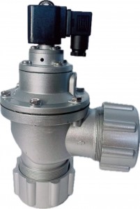
I. Product OverviewThe DMF-Z-40 pulse valve is a right-angle type valve, with a 90℃ angle between its inlet and outlet. This unique structural design gives it significant advantages in installation and connection. It is especially suitable for the connection between the air storage tank and the dust removal blowpipe, ensuring smooth gas flow and providing the required cleaning gas pulses for the dust removal system. As the “switch” for compressed air in the cleaning blowpipe system of pulse bag dust collectors, it plays a vital role in the entire dust removal process, directly determining the efficiency and effectiveness of filter bag cleaning by the dust collector.II. Working PrincipleThe working principle of the DMF-Z-40 pulse valve is based on electromagnetic control and gas circuit switching. When the pulse valve is not energized, high-pressure gas enters the lower air chamber from the inlet. At this time, the gas slowly enters the decompression chamber through the constant pressure pipeline between the upper and lower shells and the throttle hole in it. Since the valve core tightly blocks the pressure relief hole under the action of the spring, the gas cannot escape, keeping the pressure in the decompression chamber the same as that in the lower air chamber. Under the elastic force of the spring, the diaphragm seals the blowpipe tightly, preventing the gas from rushing out.When the pulse valve receives the electrical signal output by the pulse blowing control instrument, the valve core lifts upward against the spring resistance under the strong action of electromagnetic force, and the pressure relief hole is opened immediately. At this time, the gas quickly escapes from the pressure relief hole. Due to the current-limiting effect of the throttle hole in the constant pressure pipeline, the gas outflow speed from the pressure relief hole is much faster than the inflow speed of the gas from the constant pressure pipe of the decompression chamber, causing the pressure in the decompression chamber to drop rapidly and become lower than that in the lower air chamber. Under the pressure difference between the upper and lower air chambers, the gas in the lower air chamber generates enough thrust to lift the diaphragm, opening the blowpipe, and a powerful gas blowing flow rushes out instantly to clean the filter bags efficiently. When the electrical signal disappears, the electromagnetic force also disappears, and the valve core resets under the action of the spring, blocking the pressure relief hole. The pressure in the decompression chamber gradually recovers, and the diaphragm seals the blowpipe again, completing a full working cycle.