Products
-

Select the Right Pulse Jet Controller to Improve Overall Dust‑Removal System Efficiency
Poor dust‑removal performance, fast filter‑bag wear and frequent pulse‑valve failures for baghouse dust collectors are often caused by improper pulse controller selection or parameter tuning, aside from filter‑bag and air‑source issues. As the command center of the cleaning system, the quality of pulse controllers greatly influences total operating costs of dust‑handling equipment.
DMK‑4CSA‑6 pulse jet controller is engineered for industrial dust‑control applications, balancing solid reliability and user‑friendly operation. Dual‑voltage input of 220VAC and 24VDC allows connection to existing plant wiring without large‑scale modification. Digital displays offer precise numerical adjustment for pulse width, blow‑off interval and cycle groups, overcoming the inaccuracy of older dip‑switch controllers.
Robust die‑cast aluminum housing delivers better resistance against dust erosion and mechanical vibration compared with ordinary plastic casings, ideal for workshops with grinding, crushing and mixing processes. Multi‑function LED indicators show power, running and output status in real time. Abnormal conditions can be located rapidly to minimize downtime and production losses.
Adjust parameters according to actual dust load: shorten blow‑off intervals under heavy dust concentration; extend intervals for light‑dust conditions to reduce actuation frequency. Optimized parameters avoid filter‑bag blinding and preserve air flow capacity. Meanwhile, fewer valve cycles extend service life of key wear parts such as valve diaphragms and filter bags, saving spare‑part expenses.
Compatible with mainstream pulse solenoid valves on the market, this controller fits most medium‑and‑small baghouse dust collectors. It can be used for new‑machine matching as well as direct replacement for worn‑out legacy pulse controllers. Simple wiring and fast on‑site commissioning deliver stable timing signals for continuous effective cleaning. It supports compliant dust emission and acts as a practical, reliable control accessory for industrial dust‑mitigation facilities.
-

DMK‑4CSA‑6 Pulse Jet Controller – The Core Brain of Baghouse Dust Collectors
Within a complete bag‑type dust removal system, the pulse jet controller serves as an essential core control unit. It directly determines the cleaning efficiency, filter bag service life and overall operational stability of dust collectors. The DMK‑4CSA‑6 pulse jet controller is specially developed for baghouse dust removal equipment, widely used in mining, building materials, metallurgy, chemical, woodworking dust treatment and other dust‑removal working conditions.
This controller supports dual‑voltage power supply: 220VAC / 24VDC, compatible with most on‑site power conditions for flexible installation and commissioning. Equipped with dual digital displays on the front panel, operators can clearly view key parameters including pulse width, blow‑off interval and cycle time. With Set and adjustment buttons, on‑site staff can modify settings quickly without complicated training. LED indicators for Power, Run and Output show real‑time working status, simplifying fault diagnosis.
The die‑cast aluminum enclosure is impact‑resistant, dust‑proof and water‑proof. It performs reliably in harsh industrial workshops with heavy dust and fluctuating ambient temperatures, protecting internal circuits from environmental damage. It drives pulse solenoid valves to trigger sequential jet‑blow actions as programmed. Instant compressed‑air shock dislodges dust accumulated on filter bags and maintains good air permeability of filter media.
Proper settings of pulse width and interval are critical. Pulse width defines how long the solenoid valve stays open for air injection, while interval sets the waiting time between two consecutive blows. Well‑tuned parameters ensure thorough cleaning and prevent excessive cycling that wears filter bags and solenoid valves, cutting maintenance and spare‑part costs.
Featuring high integration and simple wiring, DMK‑4CSA‑6 is compatible with most right‑angle and submerged pulse valves. It is a cost‑effective option for new dust‑removal projects as well as retrofitting old dust collectors, helping dust‑removal systems operate stably to meet emission standards.
-

DMF-Z-25 Explosion-proof Pulse Jet Valve
Function & Application (English Version)
This model DMF-Z-25 straight-through pulse jet valve (Accu-Pulse brand) is a key pneumatic control component for industrial dust removal systems, equipped with an explosion-proof electromagnetic coil.Main Functions
- It serves as an air injection switch for dust collectors. Receiving electrical pulse signals from the controller, it instantly opens and closes to release compressed air.
- It generates high-pressure airflow shockwaves to blow off dust accumulated on filter bags / filter cartridges inside dust removal equipment.
- The matched explosion-proof solenoid coil enables safe operation in flammable and explosive working environments.
Working Principle
When the solenoid coil gets a pulse signal, the internal pilot structure is activated. The pressure balance inside the valve breaks, the valve diaphragm opens rapidly, and compressed air surges into the filter chamber for dust cleaning. Once the signal disappears, the valve automatically closes to finish one ash-blowing cycle.Main Purposes
- Widely installed on pulse bag dust collectors, cartridge dust collectors and other industrial dust removal equipment.
- Periodically cleans filter elements to prevent filter media blockage, maintain stable air permeability and continuous dust collection efficiency.
- Explosion-proof design satisfies application requirements in industries including chemical processing, grain processing, metallurgy, coal dust treatment and other hazardous locations with combustible dust.
Key Features
- Straight-through structure (DMF-Z series), DN25 connection size, quick response for pulse injection.
- Explosion-proof electromagnetic coil, reliable sealing, stable performance under continuous cyclic operation.
- Quick coupling connection type for easy on-site installation, disassembly and maintenance.
-

Remote Pilot Control Box (3-circuit Remote Pilot Valve Box)
1. Product Overview
This unit is specially designed to match the G353A046 air-operated submerged pulse jet valve mentioned previously.G-series air-operated pulse jet valves have no built-in solenoid valves and require external pilot valves for actuation. This is an integrated multi-channel pilot solenoid valve control box, commonly known as remote pilot box, integrated pilot valve box or remote pulse control box in the industry.
The model shown is the 3-output version (capable of driving 3 air-operated pulse valves simultaneously). The vacant positions support expansion to 4-way, 5-way, 6-way, 8-way and other specifications.
2. Component Breakdown
- Housing: Sealed die-cast aluminum alloy enclosure with IP65 dustproof and waterproof rating. Equipped with mounting brackets, suitable for dusty environments in dust collector workshops and outdoor installation.
- Central large fitting: Cable waterproof cable gland, inlet for power cable and signal wire from pulse controller.
- 3 outlets with blue quick connectors: Pilot air supply outlets. Air hoses connect to the pilot interface on top of G353A046 pulse jet valves.
- Vacant mounting flanges: Extra space inside the box to install additional pilot solenoid valves for expanding output channels.
- Internal components: Built-in miniature 3/2-way pilot solenoid valves (RCA3D micro pilot valves). They receive electrical signals from pulse controllers and output control air to actuate main pulse valves.
3. Working Principle
- The pulse controller sends electrical signals to this control box.
- The built-in micro pilot solenoid valves energize and switch sequentially, delivering controlled compressed air.
- Control air is routed via flexible hoses to the G353A046 air-operated pulse jet valves.
- The pulse valve diaphragm depressurizes and opens to complete pulse jet cleaning for filter bags.
Core logic: Electrical signal → Pilot Box → Pneumatic control signal → Air-operated pulse jet valve4. Key Advantages (vs. separately installed individual pilot valves)
- Centralized wiring & full protection
All pilot solenoid valves are enclosed inside the aluminum housing to avoid erosion from dust and moisture, greatly reducing pilot valve failure rate.
- High-temperature isolation
The air tank and pulse valves of dust collectors operate at relatively high temperatures. The pilot box can be mounted far from hot air tanks, keeping electrical components away from high heat and extending coil service life.
- Explosion-proof friendly solution
The main air-operated pulse valve contains no electrical parts. All electrical coils are concentrated inside an independent pilot box, making it easy for retrofits of explosion-proof dust removal projects.
- Simplified wiring
Only one main cable feeds into the box; separate wiring for each pulse valve is eliminated, reducing on-site piping work.
- Convenient maintenance
Troubleshooting is centralized at one location, eliminating the need to inspect scattered pilot valves one by one around each air tank.
5. Compatible List (Critical for Foreign Trade Supporting Sales)
- Matched pulse jet valves: ASCO G353A046, G353A050, domestic DMF-Y air-operated submerged pulse jet valves
- Optional coil voltages: DC24V (most common), AC110V, AC220V
- Channel options: 3-way, 4-way, 6-way, 8-way, 10-way, 12-way (customizable)
- Operating medium: Dry compressed air
- Applicable systems: Pulse cleaning systems for baghouse dust collectors and cartridge dust collectors
6. Typical Application Scenarios
Asphalt mixing plants, cement plants, metallurgy facilities, waste incineration plants, chemical explosion-proof dust removal equipment; all dust removal projects adopting remote air-operated pulse jet valves. -

G353A046 Remote Pilot Submerged Pulse Jet Valve
1. Basic Identification
- Model: G353A046 (AASF 353 Series Pulse Jet Valve)
- Serial No.: S346374
- Type: Remote air pilot submerged pulse jet valve (without built-in solenoid valve, actuated by external air supply)
Note: The model with built-in coil is SCG353A046; models starting with G stand for air pilot version, which requires an external small pilot solenoid valve for control.2. Parameter Interpretation from Nameplate
- ORF. 52 mm: Orifice diameter 52 mm
- PIPE 1-1/2″: Connection size 1.5 inch (DN40)
- MEDIA AIR: Applicable medium: compressed air
- Operating pressure: 0.35 ~ 8.5 bar
- Valve body material: Die-cast aluminum alloy with anti-corrosion coating
- Standard seal: NBR nitrile rubber; FKM fluororubber optional for high-temperature working conditions
3. Structure & Working Principle
-
Structure Type: Submerged Pulse Jet Valve
The valve is installed inside the air tank. The airflow discharges directly with much lower resistance than angle-type valves, delivering stronger jet force and higher flow capacity. It is a mainstream solution for bag dust collectors.
-
Actuation Mode: Remote Pilot Operation
The quick-connect fitting on the top connects to the control air supply. A pulse controller drives an external small solenoid valve. Once pressure relief occurs, the diaphragm opens rapidly to release compressed air instantly for pulse cleaning of filter bags / filter cartridges.
✅ Advantages: No electrical components on the main valve, suitable for high-temperature, dusty and hazardous explosion-proof environments.4. Key Features
- Ultra-fast opening & closing response, instant release of compressed air for high-efficiency dust cleaning.
- Large flow passage design with 52 mm orifice, supporting simultaneous jet cleaning for multiple filter bags on large dust removal compartments.
- Long-service-life diaphragm assembly with double-diaphragm structure, anti-fatigue for high-frequency pulse operation.
- Main valve adopts spring-free structure for lower failure rate.
- Quick-connect fitting on top; no PTFE tape required for convenient pilot air pipe installation.
5. Typical Application Scenarios
- Baghouse dust collectors, cartridge dust collectors and industrial dust extraction systems
- Cement plants, steel mills, metallurgy plants, asphalt mixing stations, waste incineration plants, powder processing industries
- Suitable for explosion-proof areas and high-temperature working conditions (FKM diaphragm for higher temperature resistance)
6. Sourcing & Replacement Key Points (for foreign trade & maintenance)
- Avoid model confusion
- G353A046: Air pilot version (this model, no coil)
- SCG353A046: Solenoid operated version with built-in coil; they cannot be directly interchanged
- Consumable spare part: diaphragm repair kit, critical stock item for after-sales service
- Installation note: Must be matched with an external pilot solenoid valve. Recommended pilot air pressure: 0.4–0.6 MPa
- Competitor alternative reference: Interchangeable with domestic 1.5″ air pilot submerged pulse valve (e.g. DMF-Y-40 air pilot type). Mounting dimensions are roughly compatible, while flow curves differ slightly.
-
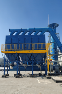
Technical Specification Report of AASF-01 Horizontal Cartridge Dust Collector
1. Basic Equipment Information
This report is compiled based on drawing No. AASF-1# Dust Removal System Equipment Layout Drawing (AASF-1). The core equipment is the horizontal cartridge dust collector, supplied as one complete set with an integrated Xuante rotary discharge valve for layout installation.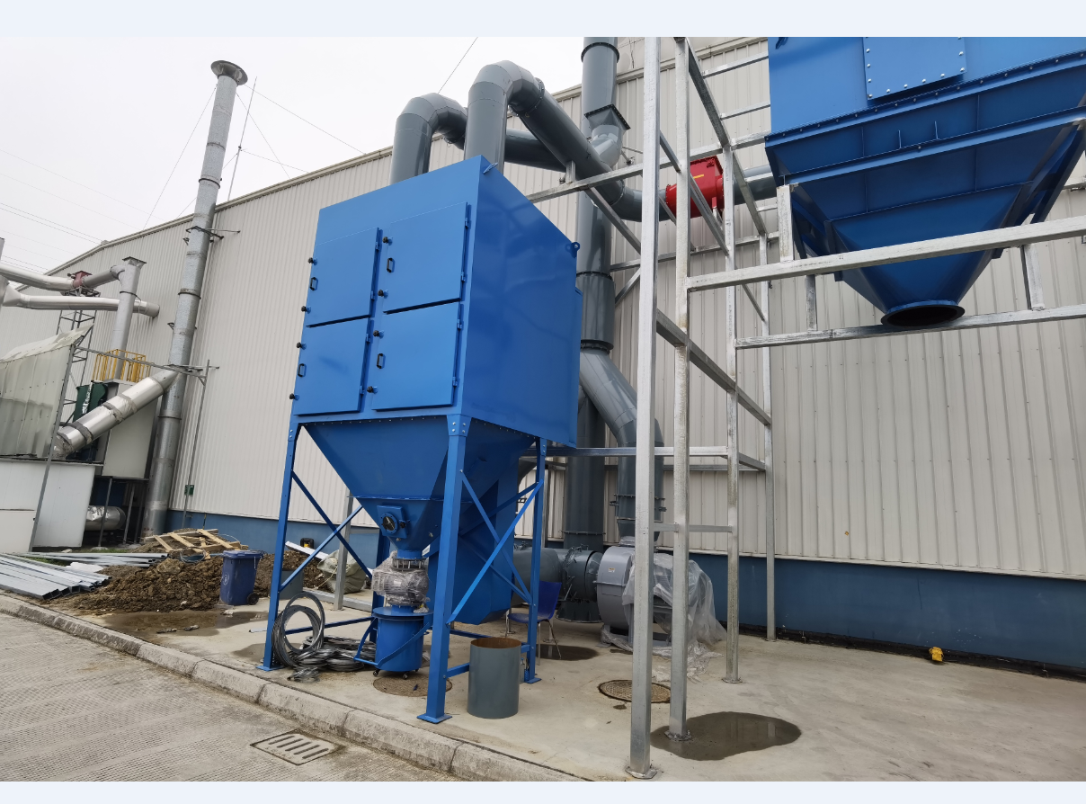
2. Core Technical Parameters of the Equipment
- Air Handling Capacity: Total air volume 21000 m³/h, equivalent to 350 m³/min;
- Main Shell Material: Q235B carbon steel plate with a thickness of 4.0 mm;
- Cleaning System Configuration: Equipped with 20 sets of electromagnetic pulse valves for pulse jet cleaning;
- Filtration Units: 40 filter cartridges in total. The filter medium is 100% polyester substrate laminated with PTFE membrane, which improves dust filtration performance as well as water and anti-sticking resistance;
- Differential Pressure Monitoring Component: 1 Dwyer differential pressure gauge is installed to real-time monitor the internal and external pressure difference of filter cartridges and judge the clogging status of cartridges;
- Air Source Pressure Regulating Component: Fitted with a Norgren pressure regulating valve to stabilize the air supply pressure for pulse cleaning;
- Ash Discharging Device: Matched with 1 set of rotary discharge valve (Xuante discharge valve) for continuous ash removal at the bottom of the dust collector.
3. Overall Dimensions & Layout of Nozzles and Flanges
3.1 Overall Outline Dimensions
- Outer frame overall length and width: 3000 mm × 3000 mm;
- Total vertical height of the equipment: 3000 mm; effective main body height: 2810 mm.
3.2 Layout of Pipe Nozzles and Flange Points
- Air outlet flanges: 2 locations in total, single air outlet diameter Φ452, vertically arranged on the front face of the equipment;
- Air supply / pulse valve connections: 4 locations in total, centrally arranged on the left vertical face for air supply to electromagnetic pulse valves;
- Discharge port screen flange: 1 location, the mounting interface at the equipment bottom for the rotary discharge valve;
- Anchor plate: 1 set, the supporting structure at the equipment bottom for leveling and fixing during on-site floor installation.
4. Manufacturing Tolerance Requirements
As specified in the drawing technical notes: All dimensions without marked tolerances shall adopt a unified tolerance of ±3 mm. All sheet metal processing, hole cutting, flange welding and anchor hole machining of the equipment shall comply with this tolerance standard to guarantee dimensional accuracy for on-site installation connection.5. Drawing Revision & Label Block Description
The drawing reserves a standard engineering revision block, including columns for Mark, Quantity, Revision Document No. and Name. Any subsequent adjustments to equipment dimensions, accessories or nozzle schemes shall be recorded and archived in this block to facilitate full-lifecycle traceability of the equipment.6. Summary
The single complete set of AASF-1 horizontal cartridge dust collector is fully equipped. Its air volume meets the dust removal requirement of 306 m³/min working condition. The combination of polyester membrane filter cartridges and pulse cleaning system is suitable for fine dust working conditions.The equipment features regular outline, clearly arranged air inlet/outlet, ash discharge port and air supply interfaces, with definite manufacturing tolerance standards and complete anchor structures. It is fully functional for on-site floor installation, continuous automatic ash discharge, online differential pressure monitoring and stable pulse cleaning. The layout dimensions on the drawing can be directly applied to equipment production, civil foundation construction and pipeline connection design.
-
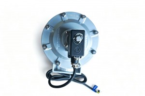
DMF‑Z‑62S Explosion‑Proof Pulse Jet Valve
DMF‑Z‑62S Explosion‑Proof Pulse Jet Valve: Reliable Choice for Hazardous‑Area Dust‑Removal Systems
The DMF‑Z‑62S explosion‑proof right‑angle electromagnetic pulse jet valve (DN62, 2.5‑inch) belongs to the classic DMF‑Z series. It is purpose‑built as a compressed‑air control switch for bag‑house dust‑cleaning systems, with an explosion‑proof solenoid coil complying with explosion‑proof standards for flammable‑dust and gas‑prone working environments. It has gained wide recognition for rapid response, stable pulsing performance and long‑term service life.
Basic Structure and Working Principle
This valve adopts a pilot‑operated double‑diaphragm design. Its inlet and outlet form a 90‑degree right‑angle layout for easy installation between air storage tanks and blow pipes of dust collectors. The internal diaphragm separates the valve into front and rear air chambers. Under normal conditions, compressed‑air fills the rear chamber via the throttle hole. Diaphragm pressure seals the outlet tightly, keeping the valve closed. Once the pulse controller delivers electric signals, the explosion‑proof solenoid activates and opens the vent hole of the rear chamber. The rear‑chamber pressure drops instantly, lifting the diaphragm to release high‑pressure compressed‑air for powerful pulse blowing on filter bags. When the electric signal stops, the solenoid resets, the rear‑chamber regains pressure and pushes the diaphragm back to seal the outlet again to finish one blowing cycleShanghai A….
Core Technical Parameters
- Nominal size: DN62 (G2‑1/2 inch internal thread connection)
- Working pressure: 0.3‑0.8 MPa (optimal operating range:0.4‑0.6 MPa)
- Optional voltages: DC24V, AC220V explosion‑proof coil
- Valve‑body material: High‑strength cast‑aluminum alloy; diaphragm material: NBR or Viton for high‑temperature options
- Ambient temperature:‑25℃ ~ +55℃; medium temperature:‑10℃ ~ +80℃
- Service lifespan: More than one‑million blowing cycles; applicable medium is dry and clean compressed‑air without oil and water.
Outstanding Advantages of Explosion‑Proof DMF‑Z‑62S
First of all, the explosion‑proof coil passes strict anti‑explosion certification. It can effectively prevent electric‑spark risks in environments with combustible dust such as coal dust, wood dust and chemical powder, satisfying safety requirements of chemical plants, cement plants, mining workshops and grain‑processing factories. Secondly, the right‑angle structure saves installation space for dust‑collector cabinets. Its internal flow channel is optimized for high airflow capacity, which improves ash‑cleaning efficiency, reduces filter‑bag blockage and extends filter‑bag service life. Thirdly, its aluminum‑alloy body is anti‑corrosion and anti‑abrasion. The high‑quality imported diaphragm delivers stable operation under continuous frequent on‑off conditions. Users can replace the diaphragm repair kit easily without disassembling the whole valve, greatly cutting maintenance costs. Besides, the threaded‑connection design makes field installation fast and firm.
-
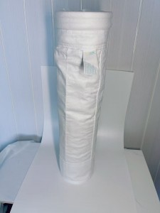
Avoidance Guide | Practical Guidelines for PTFE Filter Bag Selection, Installation and Maintenance
With normalized environmental rectification, many factories still face problems including filter bag damage, sharp pressure difference rise, shortened service life and excessive emissions after blindly replacing PTFE filter bags. Such failures rarely result from material defects, but improper selection, non-standard installation, inadequate maintenance and mixed process application. Based on front-line engineering practice, this article sorts out a complete set of schemes for PTFE filter bag classification and selection, installation risk avoidance, service life extension and cost optimization, for reference of environmental protection operation and maintenance personnel, purchasers and equipment engineers.1. Distinguish Product Types to Avoid Blind Procurement: Differences Between Three Types of PTFE Filter Bags
The PTFE filter bag market is mixed with uneven products, with a maximum price gap of 100%. The three types apply to totally different working conditions, causing frequent procurement pitfalls:1.1 All-PTFE Needle Felt Filter Bags
Woven with 100% pure PTFE fibers without mixed auxiliary materials, it boasts optimal corrosion resistance, temperature resistance and mechanical strength with the highest cost. It adapts to extreme working conditions such as municipal waste incineration and high-corrosion smelting, with a service life of 8 to 10 years. Low-cost composite products shall never be substituted, otherwise rapid damage will occur in short-term operation.1.2 Substrate Composite PTFE Filter Bags
Adopting PPS or glass fiber as the base cloth and compounding PTFE fibers on the surface, it delivers moderate cost performance, suitable for flue gas with medium corrosion and temperature below 200℃, widely used in thermal power and cement industries. Its main defect is that the bottom base cloth is prone to corrosion and fracture under high-temperature and strong-corrosion environments, so it is only applicable to production lines with stable working conditions.1.3 ePTFE Laminated PTFE Filter Bags
It is produced by laminating expanded PTFE microporous membrane on ordinary filter materials, featured with high-precision dust removal, good air permeability and easy ash cleaning, mainly used for ultra-low emission renovation. Its disadvantage is the thin and fragile membrane layer, which is easy to delaminate and damage when rubbed by sharp hard objects, so it is not recommended for working conditions with severe dust abrasion.2. Four Common Selection Misunderstandings Made by 90% of Factories
Misunderstanding 1: Only Focus on Material While Ignoring Seam Technology
PTFE cannot be sewn by hot-melt stitching; ordinary thread stitching leaves gaps with poor corrosion resistance, and seams always crack first during operation. Qualified filter bags must adopt the hot-melt welding process with seamless compression bonding to prevent dust leakage from pinholes and seam corrosion. Purchasers must verify the welding process before procurement. -
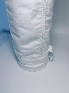
Corrosion and Temperature Resistant King of Industrial Filtration – A Comprehensive Analysis of PTFE Filter Bags
In the fields of industrial environmental protection dust removal and fluid filtration, working conditions featuring high temperature, strong acid and alkali, and high-humidity corrosion have always been major pain points for filter media. Conventional polyester, PPS and aramid filter bags are prone to aging, damage and filtration failure, resulting in excessive exhaust emissions, production line shutdowns and soaring operation and maintenance costs. Known as the “King of Plastics”, Polytetrafluoroethylene (PTFE) filter bags have become essential filtration products for harsh working conditions relying on excellent material stability. They are widely applied in flue gas dust removal, chemical water treatment and solid waste disposal, serving as the core filter material for current ultra-low emission renovation.1. Material Principle: Why Is PTFE Suitable for Extreme Working Conditions?
PTFE filter bags are made of high-purity PTFE fibers, divided into three mainstream types: integral PTFE needle felt, substrate composite PTFE and ePTFE laminated filter bags. With extremely stable chemical bonds in the molecular structure, they have four inherent properties that perfectly solve the defects of traditional filter media.First, outstanding universal temperature resistance. Virgin PTFE can stably withstand flue gas at 240℃-260℃ for a long time, with an instantaneous peak temperature resistance of 280℃. It will not shrink, harden or crack under temperature fluctuations caused by boiler startup and shutdown or kiln temperature rise; it also maintains stable performance at low temperatures, adapting to both high-temperature dust removal and low-temperature chemical fluid filtration scenarios.Second, extreme chemical corrosion resistance. PTFE features complete chemical inertness, covering the full pH range of 0 to 14. It resists erosion by hydrochloric acid, sulfuric acid, caustic soda, fluorinated materials and organic solvents. For flue gas containing hydrogen chloride, sulfide and heavy metal vapor from waste incineration, acid-base chemical filtrate and corrosive dust from non-ferrous metal smelting, PTFE can operate stably for a long time to avoid filter bag perforation and fiber pulverization caused by corrosion.Third, dust-repellent and easy ash cleaning. Boasting ultra-low surface energy, PTFE is naturally hydrophobic and oleophobic with near-zero water absorption. It will not harden and cake under high-humidity flue gas and oil-containing dust conditions. Dust only adheres to the filter bag surface instead of penetrating into fibers, and can be removed rapidly via pulse ash cleaning, reducing ash cleaning resistance by 30% and cutting fan energy consumption significantly.Fourth, controllable filtration accuracy for ultra-low emission compliance. Especially for laminated PTFE filter bags adopting surface filtration principle, they can accurately intercept ultrafine particles as small as 0.3μm, easily keeping flue gas emission concentration below 5mg/Nm³. It meets national ultra-low emission standards for thermal power and hazardous waste industries, outperforming the deep filtration mode of ordinary filter media.2. Five Core Application Scenarios Solving Industrial Pain Points
2.1 Municipal Domestic Waste and Hazardous Waste Incineration Industry
Incineration flue gas contains multiple hazards including high temperature, acid corrosion, dioxins and heavy metals, while ordinary filter bags will be scrapped due to corrosion within 3 to 6 months. PTFE filter bags can realize synchronous dust removal and trace harmful substance adsorption, with a service life of 6 to 10 years. They avoid production shutdowns caused by frequent filter bag replacement and act as the preferred filter material for environmental compliance renovation of hazardous waste disposal plants.2.2 Thermal Power and Biomass Power Generation Industry
Flue gas after desulfurization and denitrification of coal-fired and biomass boilers has complex components and sulfur-nitrogen corrosive substances, which easily damage dust removal filter bags. PTFE filter bags resist erosion of acid-base flue gas with stable operating pressure difference, applicable to dust removal systems of million-kilowatt-level power units to ensure long-term qualified emissions of power plants.2.3 Fine Chemical and Pharmaceutical Manufacturing Industry
It is mainly used for filtration of chemical acid-base mother liquor, purification of organic solvents and tail gas dust removal in pharmaceutical production. It will not precipitate harmful substances to pollute raw materials and resists swelling caused by organic solvents, balancing filtration purity and production safety for high-purity material production conditions.2.4 Non-ferrous Metal and Smelting Industry
Smelting flue gas contains fluorine and chlorine corrosive particles with strong abrasiveness. Featuring dual advantages of wear and corrosion resistance, PTFE withstands scouring and abrasion of flue gas, recovers valuable metal dust, and realizes a balance between environmental emission reduction and material profit growth.2.5 Industrial Water Treatment Industry
Applied to industrial wastewater pretreatment, precision filtration of acid-base wastewater and impurity removal of electroplating wastewater, PTFE liquid filter bags feature excellent impermeability and electroplating solution corrosion resistance, with high suspended solid interception accuracy. They can be cleaned and reused repeatedly to reduce consumable costs of water treatment systems.3. Objective Advantages and Disadvantages Analysis
Advantages: Excellent temperature and corrosion resistance, hydrophobicity and moisture resistance, long service life, high emission compliance rate and low maintenance frequency. The only disadvantage lies in high initial procurement cost. However, considering long-term operation and maintenance cost, shutdown loss and environmental penalty cost within 3-5 years, its comprehensive cost performance is far higher than low-cost filter materials. Usage Precautions: Avoid long-term contact with molten alkali metals and high-temperature elemental fluorine; it is applicable to all other industrial working conditions. -

Glass Fiber Filter Bags – A Core Filter for High-Temperature and Complex Working Conditions
Glass Fiber Filter Bags – A Core Filter for High-Temperature and Complex Working Conditions
In the field of industrial dust removal and flue gas purification, glass fiber filter bags have become the core filtering medium for harsh working conditions due to their excellent high-temperature resistance and corrosion resistance. As a filtering material made of high-purity glass fiber as the base material, woven or needle-punched through special processes, it breaks the application limitations of traditional filter materials in high-temperature and corrosive environments, providing key support for environmental compliance in industries such as steel, chemical industry, and cement.The core advantages of glass fiber filter bags stem from the in-depth integration of the inherent material properties of glass fibers and process innovation. In terms of temperature resistance, their long-term service temperature can reach 260℃, and the instantaneous temperature resistance can be as high as 350℃, far exceeding conventional filter materials such as polyester and aramid. They can stably handle high-temperature flue gas without additional cooling devices, significantly reducing system energy consumption. At the same time, they possess excellent chemical stability, capable of long-term operation in acidic and alkaline environments with a pH value of 2-12, effectively resisting corrosion from harmful gases such as SO₂ and HCl in industrial flue gas. Moreover, they have no risk of electrostatic accumulation, and their Class A non-combustible property makes them suitable for explosion-proof scenarios such as flammable dust, ensuring high safety.Optimized structural design further enhances their filtering performance. The three-dimensional microporous network structure constructed by single fiber dispersion technology has a porosity of over 80%, forming gradient filtering channels. It not only achieves energy-saving operation with low initial pressure difference (≤120Pa) but also achieves a retention rate of over 99.9% for particles above 0.3μm through deep filtration mechanism. To address the inherent brittleness of glass fiber materials, the industry has improved through technologies such as PTFE membrane coating and flexible impregnation, increasing the folding resistance life of filter bags by 3-5 times, reducing dust adhesion, and extending the ash cleaning cycle. Under standard working conditions, the service life can be as long as 3-5 years.In practical applications, glass fiber filter bags have penetrated into multiple key industrial fields. In the steel industry, they are used for dry dust removal of blast furnace gas, capable of handling high-temperature flue gas with an air volume exceeding 1 million m³/h; in the alkaline dust environment at the tail of cement kilns, glass fiber filter bags treated with PTFE membrane coating can effectively resist erosion from CaO and MgO, maintaining stable filtering efficiency up to standard; in the field of waste incineration and hazardous waste treatment, their high-temperature and corrosion resistance can cope with flue gas temperatures of 180-260℃, while efficiently capturing pollutants such as dioxins and heavy metals, making the emission concentration meet strict EU standards. In addition, in high-temperature, high-humidity or highly corrosive working conditions such as biomass power generation and chlor-alkali chemical industry, glass fiber filter bags also demonstrate irreplaceable value through precise adaptability to working conditions.Scientific selection and maintenance are crucial to exerting the performance of glass fiber filter bags. During selection, the type of filter material should be matched according to flue gas temperature and corrosive component concentration; for example, caution should be exercised when the concentration of Cl⁻ and SO₃ is high. Pre-coating with Ca(OH)₂ should be carried out in the initial operation stage, and the injection pressure should be controlled at 0.2-0.3MPa to avoid fiber damage caused by high-pressure impact. Detecting the integrity of filter bags every 6 months through differential pressure method or fluorescent penetrant inspection can significantly extend their service life and maximize technical and economic benefits. -
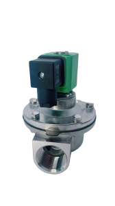
The Working Principle of Pulse Valves: Mechanism, Stages and Core Components
Pulse valves are the core control components of industrial pulse jet cleaning systems, widely used in dust collection equipment to realize efficient cleaning of filter bags. Their core function is to convert continuous compressed air into intermittent, high-speed pulse airflow through precise on-off control. The stable and rapid operation of pulse valves relies on a scientific pressure difference control mechanism, with the diaphragm assembly and solenoid pilot valve playing a pivotal role. This article will elaborate on the working principle of pulse valves in detail, including their core component collaboration and the three key stages of operation.Core Components Involved in the Working Mechanism
Before exploring the working principle, it is necessary to understand the core components that drive the operation of pulse valves, as their coordinated work ensures the valve’s reliable performance. Industrial pulse valves (mainly pilot-operated types, the most widely used category) are composed of four key parts:The valve body serves as the main structural framework, providing channels for compressed air flow and mounting positions for internal components. The solenoid pilot valve acts as the “control switch,” responsible for receiving electrical signals from the dust collector controller and regulating the pressure in the diaphragm upper chamber. The diaphragm assembly (including the pulse valve diaphragm) is the core executive component, whose movement directly controls the on-off of the main air channel. The reset spring assists the solenoid pilot valve in resetting after power failure, ensuring the diaphragm returns to the closed position stably.Among these components, the diaphragm is the key vulnerable part. Made of rubber, PTFE, or fabric-reinforced materials, it must have excellent elasticity, wear resistance, and fatigue resistance to withstand frequent pressure changes and cyclic movements. The solenoid pilot valve, on the other hand, requires high response speed to ensure the pulse valve can complete the on-off action in milliseconds.Three Stages of Pulse Valve Operation
The working process of pulse valves is based on the pressure difference control principle, which can be clearly divided into three stages: standby, opening (pulse jet), and resetting. Each stage is driven by the cooperative operation of the solenoid pilot valve and diaphragm, realizing precise control of compressed air.1. Standby Stage: Pressure Balance Maintains Closure
In the standby state, the dust collector is in normal filtration mode, and the pulse valve remains closed to avoid unnecessary air consumption. At this time, the solenoid pilot valve is de-energized and in the closed position, blocking the exhaust channel connected to the upper chamber of the diaphragm. Compressed air from the air source enters the upper chamber of the diaphragm through a built-in small air passage in the valve body, while a portion of the air remains in the lower chamber of the diaphragm.Due to the structural design, the pressure in the upper chamber of the diaphragm is slightly higher than that in the lower chamber. This pressure difference generates a downward force, pressing the diaphragm tightly against the valve seat of the main air channel. As a result, the main air channel is completely closed, and compressed air cannot pass through, ensuring the dust collector can stably filter dust without air leakage.2. Opening Stage: Reverse Pressure Difference Triggers Pulse Jet
When the filter bags of the dust collector accumulate a certain amount of dust, the controller sends an electrical cleaning signal to the solenoid pilot valve. Upon receiving the signal, the solenoid pilot valve is instantly energized and opens, connecting the upper chamber of the diaphragm to the atmospheric environment through the exhaust channel.The compressed air in the upper chamber of the diaphragm is quickly discharged to the atmosphere through the opened pilot valve, causing the pressure in the upper chamber to drop sharply in a short time. Meanwhile, the pressure in the lower chamber of the diaphragm remains unchanged (consistent with the air source pressure). This rapid pressure change forms a reverse pressure difference between the upper and lower chambers of the diaphragm, with the upward force in the lower chamber overcoming the downward force in the upper chamber.Under the action of this reverse pressure difference, the diaphragm is pushed upward rapidly, opening the main air channel of the pulse valve. Compressed air from the air source then rushes through the main channel to the blowpipe at high speed, generating a strong pulse airflow. This airflow is ejected through the nozzles on the blowpipe, penetrating the filter bags and causing them to expand and vibrate, thereby blowing off the dust accumulated on the surface of the filter bags to achieve cleaning.The duration of this opening stage (i.e., the pulse width) is usually adjustable between 0.1-0.5 seconds, depending on the dust properties and filter bag specifications. High-quality pulse valves can complete the opening action in tens of milliseconds, ensuring the pulse airflow is concentrated and powerful.3. Resetting Stage: Pressure Recovery Restores Closure
After the preset cleaning cycle ends, the dust collector controller cuts off the power supply to the solenoid pilot valve. The solenoid pilot valve resets under the action of the internal reset spring, closing the exhaust channel again and blocking the connection between the upper chamber of the diaphragm and the atmosphere.Compressed air from the air source re-enters the upper chamber of the diaphragm through the built-in small air passage, gradually increasing the pressure in the upper chamber. As the pressure rises, the pressure difference between the upper and lower chambers is restored to the standby state, and the diaphragm is pressed back to the valve seat by the downward pressure of the upper chamber, closing the main air channel.At this point, the pulse valve completes a full working cycle and returns to the standby state, waiting for the next cleaning signal. The entire process is repeated continuously, ensuring the dust collector maintains stable filtration efficiency by regularly cleaning the filter bags. -
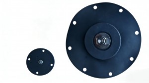
Selection Guide and Maintenance Tips for Pulse Valve Diaphragms
Pulse valve diaphragms are vulnerable components in dust collection systems, and their service life is affected by material selection, working conditions, and maintenance practices. Proper selection and regular maintenance can significantly extend the diaphragm’s lifespan, reduce downtime, and lower operating costs. This article provides a comprehensive guide to diaphragm selection and maintenance.Key Factors for Diaphragm Selection
The selection of pulse valve diaphragms should be based on actual working conditions, focusing on the following four core factors:Material compatibility is the primary consideration. It is necessary to ensure that the diaphragm material is compatible with the working medium (compressed air, dust, or other gases) and the surrounding environment. For example, in chemical plants with corrosive gases, PTFE diaphragms should be selected; for general dust collection systems, rubber diaphragms can meet the requirements. In oil-containing compressed air environments, nitrile elastomeric diaphragms with oil resistance are preferred.Temperature range is another critical factor. Diaphragm materials have specific temperature tolerance limits, and exceeding this range will accelerate material degradation, leading to premature cracking or hardening. For high-temperature environments such as metallurgical or cement plants, high-temperature resistant materials like PTFE or special rubber should be used; for normal temperature environments, ordinary rubber diaphragms are sufficient. It is recommended to reference the manufacturer’s specifications to ensure temperature compatibility.Application pressure must match the diaphragm’s design pressure. Exceeding the maximum pressure rating will cause diaphragm rupture, while insufficient pressure may affect sealing performance. Fabric-reinforced diaphragms are suitable for high-pressure systems (above 0.6MPa), while ordinary rubber diaphragms are applicable for medium and low-pressure systems (0.3-0.6MPa). It is essential to confirm the system pressure before selection.Flexibility and endurance are crucial for long-term operation. In systems with high-frequency pulse cycles (e.g., more than 10 times per minute), diaphragms with good fatigue resistance, such as fabric-reinforced or high-quality elastomeric types, should be selected. These materials can maintain elasticity and sealing performance after millions of cycles, reducing replacement frequency.